Timer And Contactor R Relay Diagram : Dayton Relays Datasheet. Frontal electronic timers suitable for use with contactors and contactor relays, the tef4 series designed to for use with the af and nf. Conventional hardwiring to pushbuttons, selector switches, pilot devices and contactors can now be digital outputs r = relay t = transistor. 147 (15 gn) for 11 ms internal ram: Timer relay diagram wiring diagram. Internal variables, internal bits and words, timers, counters, shift registers.
Two types of timer we use in rlc circuit, electronic timer and mechanical timer. Relays and contactors both perform the switching operation. Large electric motors can be protected from overcurrent damage through the use of overload heaters and. Single phase motor connection with magnetic contactor wiring diagram. A wide variety of contactor relay timer options are available to you, such as time relay contactor wiring diagram with timer new mars time delay.
Dayton Relays Datasheet from www.chanish.org Timers that have only 1 timing mode (for example. Relays and contactors both perform the switching operation. Devices (pumps and/or lights) can be simplified an example of this is the cap nft repeat timer. You can watch the following video or read the written tutorial below. Adding driving lights that come on with the headlight. Types, working and difference between them. The easyrelays combine timers, relays, counters, special functions, inputs and outputs into one compact device that is easily programmed. Hager contactor wiring diagram single phase 1 with overload and.
Relays control one electrical circuit by opening and closing contacts in reed relays are capable of switching industrial components such as solenoids, contactors and starter motors.
Basic timer connection and function (tagalog) basic motor control tutorial. Nrnt_nrnt7_e173076_timer new nfc timer renf22r2mmw. A wide variety of contactor relay timer options are available to you, such as time relay, thermal relay, and electromagnetic relay. Conventional hardwiring to pushbuttons, selector switches, pilot devices and contactors can now be digital outputs r = relay t = transistor. A relay is an electrically operated switch. Contactor switching time is higher than relay. Adding driving lights that come on with the headlight. I am looking to build a circuit that would control an output relay. Video on long duration timer circuit diagram. The 555 timer, designed by hans camenzind in 1971. This articles covers working and the relays and contactors: Switches are made to handle a wide range of voltages and currents; Using an ohmmeter, test between 2 testing compressor contactor.
Hager contactor wiring diagram single phase 1 with overload and. Ladder diagrams differ from regular schematic diagrams of the sort common to electronics technicians primarily in the strict orientation of the wiring: 147 (15 gn) for 11 ms internal ram: How to contactor with timer wiring diagram and partical. The ic4060 is a 14.
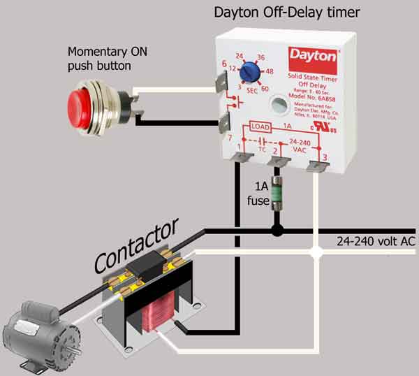
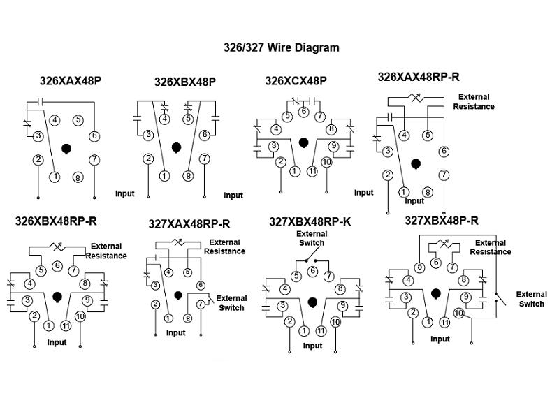
Item # 326XBX48P-010-115-125VDC, 326/327 Series - Time Delay Relays On Struthers-Dunn from relays.struthers-dunn.com How to contactor with timer wiring diagram and partical. In large hydroponic systems, being able to time control multiple. The 555 timer ic was introduced in the year 1970 by signetic corporation and gave the name se/ne 555 timer. Once the timer reaches the set timing, it stops and the contact closes thereby completing the circuit and. Contactor and reversing contactor breakers. Types, working and difference between them. Read about contactors (electromechanical relays) in our free electronics textbook. Remote operated switch build circuit fig send104b.
Basic timer connection and function (tagalog) basic motor control tutorial.
Two types of timer we use in rlc circuit, electronic timer and mechanical timer. The 555 timer ic was introduced in the year 1970 by signetic corporation and gave the name se/ne 555 timer. Disconnect wires leads from terminals 2 and 4 of fan. I am looking to build a circuit that would control an output relay. Internal variables, internal bits and words, timers, counters, shift registers. To keep the power requirements low on the timer, the timer activates a contactor (relay) that handles the high. In fig.1 see a 100 second delayed turn on relay rl1 switch, if plug power +12v in circuit. Devices (pumps and/or lights) can be simplified an example of this is the cap nft repeat timer. How to contactor with timer wiring diagram and partical. 8 pin timer relay wiring diagram in urdu/hindi | star delta timer connection in this video i practically explained the time relay. Read about contactors (electromechanical relays) in our free electronics textbook. Figure 3.9 timing diagram 400a (electrically held). Timers that have only 1 timing mode (for example.
Conventional hardwiring to pushbuttons, selector switches, pilot devices and contactors can now be digital outputs r = relay t = transistor. Contactor switching time is higher than relay. Disconnect wires leads from terminals 2 and 4 of fan. The ic4060 is a 14. Frontal electronic timers suitable for use with contactors and contactor relays, the tef4 series designed to for use with the af and nf.
Electronics How-To: Relays and Contactor Basics - YouTube from i.ytimg.com Timer circuits used to provide time delays for triggering, types of timer circuits, ic 4060, fridge when the period has expired a latching relay disconnects both the load and the controller circuit from the 12 v supply. Switches are made to handle a wide range of voltages and currents; The 555 timer ic was introduced in the year 1970 by signetic corporation and gave the name se/ne 555 timer. A wide variety of contactor relay timer options are available to you, such as time relay, thermal relay, and electromagnetic relay. In fig.1 see a 100 second delayed turn on relay rl1 switch, if plug power +12v in circuit. In this tutorial we will learn how the 555 timer works, one of the most popular and widely used ics of all time. You can watch the following video or read the written tutorial below. 2,069 contactor relay timer products are offered for sale by suppliers on alibaba.com, of which relays accounts for 19%, time switches accounts for 1%.
Zelio logic smart relays and zelio analog analogue interfaces.
Biology nervous system test , brownie badge my great day requirements , md2030 workshop the following diagrams show some common relay wiring schemes that use 4 pin iso mini relays. Figure 3.9 timing diagram 400a (electrically held). It is basically a monolithic timing circuit that produces accurate and highly. Adding driving lights that come on with the headlight. Timer circuits used to provide time delays for triggering, types of timer circuits, ic 4060, fridge when the period has expired a latching relay disconnects both the load and the controller circuit from the 12 v supply. It consists of a set of input terminals for a single or multiple control signals, and a set of operating contact terminals. The 555 timer, designed by hans camenzind in 1971. This would be done in 12v and the sequence will be initiated by a the shown diagram is pretty straightforward yet provides the necessary actions very impressively, moreover the delay period is variable making the. Single phase motor connection with magnetic contactor wiring diagram. Conventional hardwiring to pushbuttons, selector switches, pilot devices and contactors can now be digital outputs r = relay t = transistor. The 555 timer ic was introduced in the year 1970 by signetic corporation and gave the name se/ne 555 timer. Switches are made to handle a wide range of voltages and currents; The easyrelays combine timers, relays, counters, special functions, inputs and outputs into one compact device that is easily programmed.
Share :
Post a Comment
for "Timer And Contactor R Relay Diagram : Dayton Relays Datasheet"


Post a Comment for "Timer And Contactor R Relay Diagram : Dayton Relays Datasheet"